Technical Documents
Specifications
Brand
ParkerProduct Type
Pneumatic Timer
Hazardous Area Certification
LCIE 866115X
Minimum Operating Pressure
3bar
Mount Type
DIN Rail
Maximum Operating Pressure
8 bar
Minimum Operating Temperature
-15°C
Maximum Operating Temperature
60°C
Standards/Approvals
NFC 23519, NFC 23514, EN 50019, EN 50014, EExe II T4code
Product Details
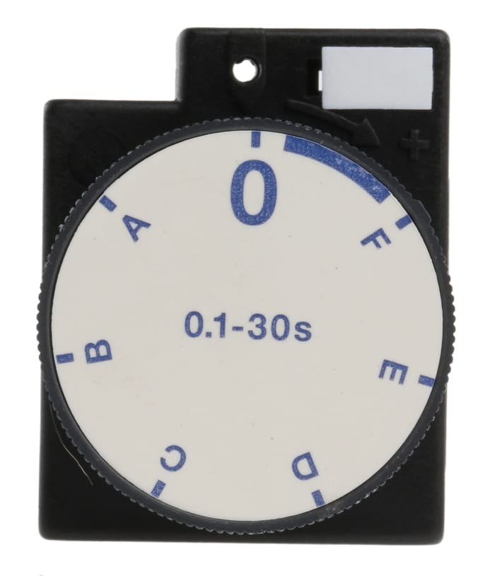
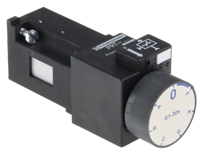
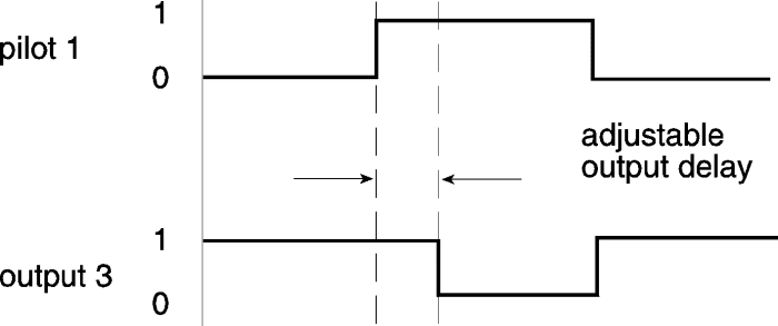
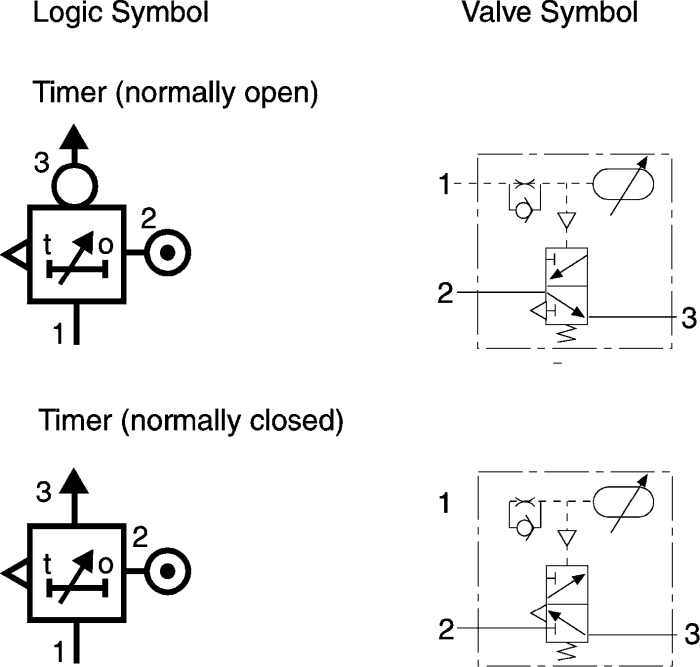
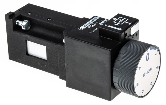
The Parker PRT series pneumatic time delay relay requires operating pressure ranging between 3bar and 8bar. This ON delay timer has a timing range from 0.1 seconds to 30 seconds. This timer has maintained input signal during an adjustable time after which a regenerated output appears. It is consists of a solenoid coil/core, operating spring, timing disk, filter and diaphragm. The core moves up into the coil when it has been energized and this leads to pressure on the diaphragm. The diaphragm moves into the top chamber which un-traps the air through the timing disk. By altering the needle valve you can adjust the amount of delay.
Note:
All the logic units require mounting on a separate 2 or 3 port base, available separately. Logic units have an input (green) and output (red) pressure indicator to show the state of the respective signal. Units are supplied with two captive screws for mounting on all types of base and sealing O-rings are in the bottom of each unit.
Stock information temporarily unavailable.
EGP 27,553.00
EGP 27,553.00 Each (ex VAT)
1
EGP 27,553.00
EGP 27,553.00 Each (ex VAT)
Stock information temporarily unavailable.
1
Technical Documents
Specifications
Brand
ParkerProduct Type
Pneumatic Timer
Hazardous Area Certification
LCIE 866115X
Minimum Operating Pressure
3bar
Mount Type
DIN Rail
Maximum Operating Pressure
8 bar
Minimum Operating Temperature
-15°C
Maximum Operating Temperature
60°C
Standards/Approvals
NFC 23519, NFC 23514, EN 50019, EN 50014, EExe II T4code
Product Details
The Parker PRT series pneumatic time delay relay requires operating pressure ranging between 3bar and 8bar. This ON delay timer has a timing range from 0.1 seconds to 30 seconds. This timer has maintained input signal during an adjustable time after which a regenerated output appears. It is consists of a solenoid coil/core, operating spring, timing disk, filter and diaphragm. The core moves up into the coil when it has been energized and this leads to pressure on the diaphragm. The diaphragm moves into the top chamber which un-traps the air through the timing disk. By altering the needle valve you can adjust the amount of delay.
Note:
All the logic units require mounting on a separate 2 or 3 port base, available separately. Logic units have an input (green) and output (red) pressure indicator to show the state of the respective signal. Units are supplied with two captive screws for mounting on all types of base and sealing O-rings are in the bottom of each unit.