Technical Document
Specifications
Brand
MicrochipFamily Name
PIC16F
Package Type
PDIP
Mounting Type
Through Hole
Pin Count
40
Device Core
PIC
Data Bus Width
8bit
Program Memory Size
8192 x 14 words, 256 B
Maximum Frequency
20MHz
RAM Size
368 B
USB Channels
0
Number of PWM Units
2 x 10 bit
Number of SPI Channels
1
Number of USART Channels
1
Number of UART Channels
0
Typical Operating Supply Voltage
2 → 5.5 V
Number of I2C Channels
1
Number of CAN Channels
0
Maximum Number of Ethernet Channels
0
Minimum Operating Temperature
-40 °C
Height
4.95mm
Number of LIN Channels
0
Dimensions
2.095 x 0.58 x 0.195in
Program Memory Type
Flash
Number of Ethernet Channels
0
Pulse Width Modulation
1 (10 bit) (CCP), 1 (10 bit) (ECCP)
Number of PCI Channels
0
Instruction Set Architecture
RISC
Number of ADC Units
1
Maximum Operating Temperature
+85 °C
Length
53.21mm
ADCs
14 x 10 bit
Width
0.58in
Product details
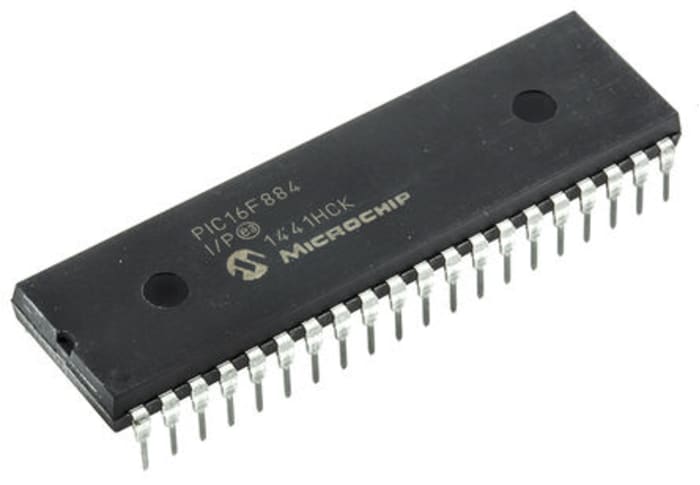
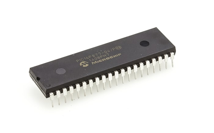
PIC16F882/883/884/886/887 8-Bit Flash Microcontrollers
The PIC16F range of microcontrollers from Microchip are 8-bit MCUs that incorporate Microchip’s PIC® architecture into a variety of pin and package options, from space efficient 14-pin devices to feature-rich 64-pin devices. Devices with Baseline, Mid-Range or Enhanced Mid-Range architecture are available with numerous different peripheral combinations, giving designers flexibility and choice for their applications.
The PIC16F882/883/884/886/887 family of microcontrollers is based upon Microchip’s Mid-Range core with an 8 level deep hardware stack and 35 instructions. These MCUs provide up to 5 MIPS, up to 14 Kbytes program memory, up to 368 bytes RAM and EEPROM of up to 256 bytes. On board is a configurable oscillator factory calibrated to ±1% accuracy.
Microcontroller Features
20 MHz Max. CPU Speed
35 Instructions
8 Level Hardware Stack
8 MHz Internal Oscillator – Selectable Output Range from 8 MHz to 31 kHz
24 I/O Pins – PIC16F882/883/886
35 I/O Pins – PIC16F884/887
Power-On Reset (POR)
Brown-Out Reset (BOR)
Power-Up Timer (PWRT)
Oscillator Start-Up Timer (OST)
Watchdog Timer (WDT)
In-Circuit Serial Programming (ICSP)
In-Circuit Debug (ICD)
Peripherals
10-bit Analogue-to-Digital Converter (ADC) - PIC16F882/883/886 11 Channels, PIC16F884/887 14 Channels
Two Capture, Compare, PWM (CCP) Modules
Enhanced Capture, Compare, PWM (ECCP) Module
Two Comparators
Two 8-bit Timers
One 16-bit Timer
Master Synchronous Serial Port (MSSP) with SPI and I2C
Enhanced Universal Synchronous Asynchronous Receiver Transmitter (EUSART)


EGP 1,859.10
EGP 371.82 Each (In a Pack of 5) (ex VAT)
Standard
5
EGP 1,859.10
EGP 371.82 Each (In a Pack of 5) (ex VAT)
Standard
5
Stock information temporarily unavailable.
Please check again later.


Technical Document
Specifications
Brand
MicrochipFamily Name
PIC16F
Package Type
PDIP
Mounting Type
Through Hole
Pin Count
40
Device Core
PIC
Data Bus Width
8bit
Program Memory Size
8192 x 14 words, 256 B
Maximum Frequency
20MHz
RAM Size
368 B
USB Channels
0
Number of PWM Units
2 x 10 bit
Number of SPI Channels
1
Number of USART Channels
1
Number of UART Channels
0
Typical Operating Supply Voltage
2 → 5.5 V
Number of I2C Channels
1
Number of CAN Channels
0
Maximum Number of Ethernet Channels
0
Minimum Operating Temperature
-40 °C
Height
4.95mm
Number of LIN Channels
0
Dimensions
2.095 x 0.58 x 0.195in
Program Memory Type
Flash
Number of Ethernet Channels
0
Pulse Width Modulation
1 (10 bit) (CCP), 1 (10 bit) (ECCP)
Number of PCI Channels
0
Instruction Set Architecture
RISC
Number of ADC Units
1
Maximum Operating Temperature
+85 °C
Length
53.21mm
ADCs
14 x 10 bit
Width
0.58in
Product details
PIC16F882/883/884/886/887 8-Bit Flash Microcontrollers
The PIC16F range of microcontrollers from Microchip are 8-bit MCUs that incorporate Microchip’s PIC® architecture into a variety of pin and package options, from space efficient 14-pin devices to feature-rich 64-pin devices. Devices with Baseline, Mid-Range or Enhanced Mid-Range architecture are available with numerous different peripheral combinations, giving designers flexibility and choice for their applications.
The PIC16F882/883/884/886/887 family of microcontrollers is based upon Microchip’s Mid-Range core with an 8 level deep hardware stack and 35 instructions. These MCUs provide up to 5 MIPS, up to 14 Kbytes program memory, up to 368 bytes RAM and EEPROM of up to 256 bytes. On board is a configurable oscillator factory calibrated to ±1% accuracy.
Microcontroller Features
20 MHz Max. CPU Speed
35 Instructions
8 Level Hardware Stack
8 MHz Internal Oscillator – Selectable Output Range from 8 MHz to 31 kHz
24 I/O Pins – PIC16F882/883/886
35 I/O Pins – PIC16F884/887
Power-On Reset (POR)
Brown-Out Reset (BOR)
Power-Up Timer (PWRT)
Oscillator Start-Up Timer (OST)
Watchdog Timer (WDT)
In-Circuit Serial Programming (ICSP)
In-Circuit Debug (ICD)
Peripherals
10-bit Analogue-to-Digital Converter (ADC) - PIC16F882/883/886 11 Channels, PIC16F884/887 14 Channels
Two Capture, Compare, PWM (CCP) Modules
Enhanced Capture, Compare, PWM (ECCP) Module
Two Comparators
Two 8-bit Timers
One 16-bit Timer
Master Synchronous Serial Port (MSSP) with SPI and I2C
Enhanced Universal Synchronous Asynchronous Receiver Transmitter (EUSART)


